

Translate this page into:
Cardiac Imaging: OCT

Hetan C. Shah, MD, DNB (CARD), FACC, FESC, FSCAI Department of Cardiology, KEM Hospital and Seth GS Medical College Mumbai Mumbai, Maharashtra, 400012 India hetancshah@gmail.com
This article was originally published by Thieme Medical and Scientific Publishers Private Ltd. and was migrated to Scientific Scholar after the change of Publisher.
Abstract
Abstract
Introduction Intracoronary imaging by means of optimal coherence tomography (OCT) provides valuable incremental information that can be used clinically to optimize stent implantation and minimize stent-related problems. Over the past decades, OCT has progressively evolved with respect to technical performance and procedural aspects.
Principle OCT is a fiberoptic wire with a rotating lens emitting near infrared (1,300 nm) light and records the light reflected from the tissue. The currently used Fourier domain-OCT allows superior image quality and faster image acquisition.
OCT in Acute Coronary Syndrome (ACS) It helps in accurate detection of actual event leading to ACS among plaque rupture, plaque erosion, and calcified nodule. OCT has an advantage over intravascular ultrasound for identification of vulnerable plaque and also detection of thin cap fibroatheroma < 65 µm.
Clinical Utility OCT helps in diagnosis of an angiographically ambiguous lesion such as dissection, thrombus, and calcified nodule. It also helps in planning different aspects of percutaneous coronary intervention such as lesion preparation, determining stent size and length and also helps in optimization of results of stent deployment.
Certain nonatherosclerotic events such as coronary arteritis can be diagnosed with OCT.
Continued advancement in technology, faster image acquisition, and more sophisticated coregistered image analysis will facilitate greater adoption through ease of use and interpretation.
Keywords
cardiac imaging
optical coherence tomography
percutaneous coronary intervention (PCI)

Introduction
Coronary angiography is being used conventionally for the evaluation of coronary anatomy and guidance of percutaneous coronary interventions (PCIs). But it cannot depict the arterial vessel wall and measure actual vessel dimensions and the morphology of culprit lesion or status of the fibrous cap neither it can directly assess the result of stent implantation.
Intracoronary imaging with the use of intravascular ultrasound (IVUS) and optimal coherence tomography (OCT) not only provides valuable additional information that helps to understand plaque morphology and to optimize stent implantation but also minimizes stent-related problems. Over the years, IVUS and OCT evolved tremendously in terms of various procedural aspects such as faster pullback, automatic vessel/lumen, and plaque burden detection and measurements, and coregistration with angiography.
Compared with other methods of imaging technique, OCT offers an exponential increase in resolution, accuracy, and speed that has been shown to enhance decision making.
OCT, which is a catheter-based invasive imaging modality using infrared light and its reflection to image the coronary wall, was originally used to image the retina. Lately, it has also been found to be useful in various fields of medicine and surgery. Currently, it is gaining importance in its use in acute coronary syndrome (ACS) as it helps determine the mechanism of plaque disruption, thrombus burden, and guiding PCI.
OCT is of particular importance in evaluating the cause of stent failure. This review discusses the role of OCT in ACS and its potential causes.
History of OCT
Mr. David Huang and Dr. Fujimoto conceived the idea of OCT imaging in 1991. They used the OCT in the study of the retina of the human eye.
Brezinski et al1 suggested the use of OCT for intravascular imaging. After that OCT was used for intracoronary imaging and now it has gained momentum over the last few years.
Principles
OCT is done with a fiberoptic wire with a rotating lens emitting near infrared (1,300 nm) light and records the light reflected from the tissue.2 Light interferometry is the technique used to analyze the reflected light signal. The result of OCT is an image of very high resolution (10 µm axially and 20 µm lateral). OCT has very low tissue penetration (1.0–3.5 mm). Multiple axial scans are obtained by simultaneous rotation and pullback of the OCT wire to develop cross-sectional images of the target vessel wall.
Procedural Steps for OCT and Image Acquisition
The OCT system comprises OCT imaging catheter, drive motor and optical coupler (DOC), OCT integrated computer system to acquire images and analyze as well as perform automatic or manual measurements after completion of image acquisition.
The imaging catheter is a 0.014-inch wire compatible with 2.7 F rapid exchange intravascular catheter with an external sheath and an internal rotating fiberoptic imaging core emitting infrared light and capturing the reflected backscattered light waves.
At present, to provide an adequate and rapid injection of contrast during image acquisition, a guide catheter of at least 6F size without side holes and coaxially alignment in the coronary artery is recommended. The outer sheath is flushed with 3 to 5 cc of contrast medium so that no blood element can enter between the optical probe and sheath. The OCT catheter is then connected to the DOC, and the catheter is advanced over the wire. The intravascular imaging catheter has three radiopaque markers. They are placed at the distal tip, imaging lens, and 50 mm proximal to the lens. The lens marker is kept just distal to the intended segment to be studied.
Enable pullback recording while injecting contrast medium (12–15 cc at the rate of 4cc/s – manually or automatically) to acquire the OCT run. Once the displacement of blood from the vessel is detected by the OCT lens, the images are automatically acquired (Fig. 1).
-
Fig. 1 Normal optimal coherence tomography (OCT) image. Normal OCT image showing three-layer structure with bright internal external elastic lamina with a thin layer of low-intensity media in between.
Fig. 1 Normal optimal coherence tomography (OCT) image. Normal OCT image showing three-layer structure with bright internal external elastic lamina with a thin layer of low-intensity media in between.
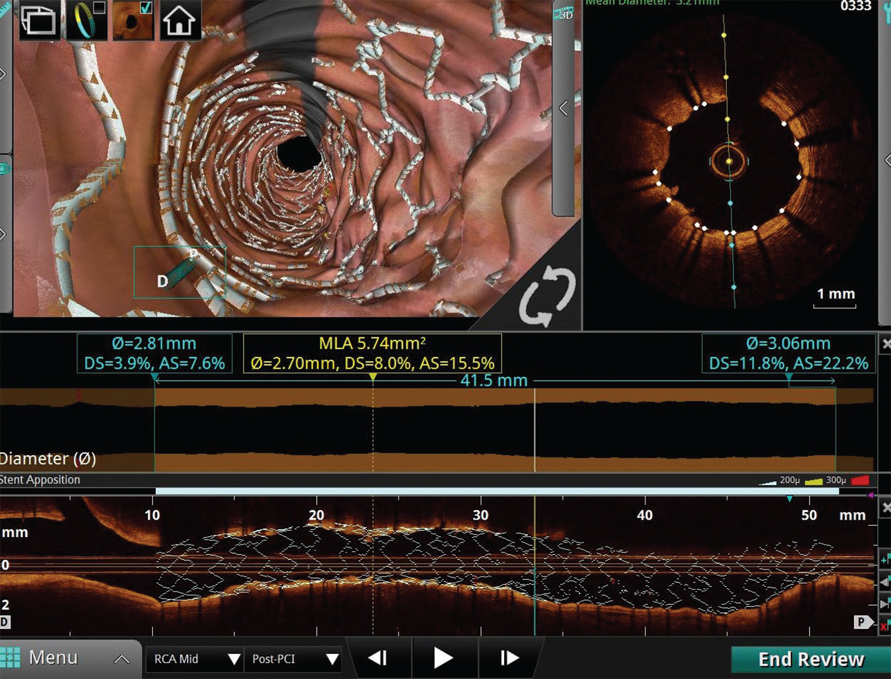
The acquired images are available for immediate review and analysis in longitudinal view, cross-sectional view, and three-dimensional view (Fig. 2).
-
Fig. 2 Longitudinal view, cross-sectional view and three-dimensional (3D) view. Longitudinal view, cross-sectional view, and 3D view of post stent placement segment showing adequate apposition and expansion.
Fig. 2 Longitudinal view, cross-sectional view and three-dimensional (3D) view. Longitudinal view, cross-sectional view, and 3D view of post stent placement segment showing adequate apposition and expansion.
OCT Interpretation
Vascular tissue layers have variable backscattering and attenuation properties as they interact with infrared light.
High backscattering by a tissue gives it a high pixel intensity (bright picture, internal and external elastic lamina [EEL], fibrous tissue), while the low backscattering will be seen as darker, low pixel intensity region (media and calcium). The second interaction that defines the tissue is attenuation. A high attenuation means light cannot penetrate the deeper tissue (lipid and red thrombus), whereas low attenuation means light passes through the tissue to a deeper level that can be seen in images (calcium and fibrotic tissue). Other features used in image interpretation are homogenous versus heterogeneous composition (fibrous plaque and lipids vs. calcium, respectively), sharp versus thin edges (calcium vs. lipids) (Table 1).
|
Lipid plaque |
Fibrotic plaque |
Calcified plaque |
|
|---|---|---|---|
|
Abbreviation: OCT, optimal coherence tomography. |
|||
|
Signal strength |
Low signal |
High signal |
Low signal |
|
Signal homogeneity |
Homogeneous |
Homogeneous |
Inhomogeneous |
|
Plaque margins |
Moderately delineated |
Poorly delineated |
Well delineated |
|
Light attenuation |
High |
Low |
Low |
|
Deep penetration |
Low |
High |
High |
The normal coronary arterial segment in OCT images appears as a three-layer structure with bright internal EEL with a thin layer of low-intensity media in between.
Artifacts
OCT images are prone to artifacts. In one study, 30.9% of images contain artifact, and these improve with operator experience.3
The most common artifact is blood swirl artifact, guidewire bias artifact, sew up artifact, and sunflower artifact (Fig. 3).
-
Fig. 3 Swirl artifact. Optimal coherence tomography image showing swirl artifact at 5 o'clock position.
Fig. 3 Swirl artifact. Optimal coherence tomography image showing swirl artifact at 5 o'clock position.
Advantages of OCT
-
Very rapid image acquisition that is easy to interpret.
-
Near spatial field resolution 10 times higher than IVUS.
-
Determination of calcium thickness (which is not possible with IVUS), total calcium arc.
-
Accurate identification of red and white thrombus.
-
Better volumetric lumen analysis for stent sizing.
-
Identification of minute irregularities in the vessel wall, for example, edge dissection.
-
Accurate poststent optimization.
Disadvantages of OCT
-
Additional contrast load.
-
Swirling artifacts.
-
Sometimes predilatation may be necessary for the pullback.
-
Inability to access aorto-ostial lesion.
-
Depth penetration is limited.
OCT in Acute Coronary Syndrome
Acute thrombosis in coronaries leads to ACS, and three major mechanisms responsible are plaque rupture, plaque erosion, and calcified nodule.4 5
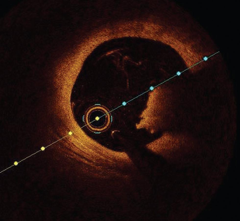
Plaque rupture is defined by an area of fibrous cap disruption where the overlying thrombus is in continuation with an underline necrotic core. The smooth muscle cells within a fibrous cap at the rupture site are sparse. It is the most common cause of death in young males and elderly females6 (Fig. 4).
-
Fig. 4 Plaque rupture. Optimal coherence tomography image showing plaque rupture at from 10 to 3 o’clock position.
Fig. 4 Plaque rupture. Optimal coherence tomography image showing plaque rupture at from 10 to 3 o’clock position.
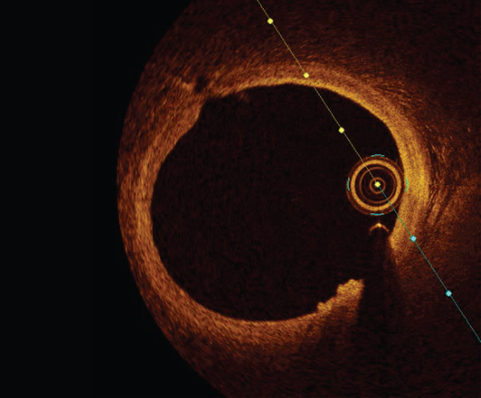
An intraluminal mass adherent to the luminal surface or floating within lumen with high (red thrombus) or low (white thrombus) is easily diagnosed with OCT (Fig. 5).
-
Fig. 5 Red thrombus. Optimal coherence tomography image showing red thrombus at 3 to 5 o’clock position.
Fig. 5 Red thrombus. Optimal coherence tomography image showing red thrombus at 3 to 5 o’clock position.
Plaque erosion is defined by an absence of fibrous cap disruption in the presence of thrombus or luminal surface irregularity without any thrombus. Definitive OCT erosion was identified by the presence of an adherent thrombus overlying an intact visualized plaque. Probable OCT erosion was defined as either with luminal surface irregularity without any thrombus or attenuation of underlying plaque by the thrombus by superficial lipid or calcification immediately proximal or distal to the thrombus7 (Fig. 6).
-
Fig. 6 Plaque erosion. Optimal coherence tomography image showing luminal irregularity without thrombus at 5 to 6 o‘clock position.
Fig. 6 Plaque erosion. Optimal coherence tomography image showing luminal irregularity without thrombus at 5 to 6 o‘clock position.
Plaque erosion is more common in women and younger men < 50 years of age. It has a strong association with smoking in premenopausal women.6 Patients with ACS (92.5%) caused by plaque erosion, who were treated with aspirin and ticagrelor without stenting, remained free of major adverse cardiovascular event (MACE) for ≤ 1 year (Erosion study).8
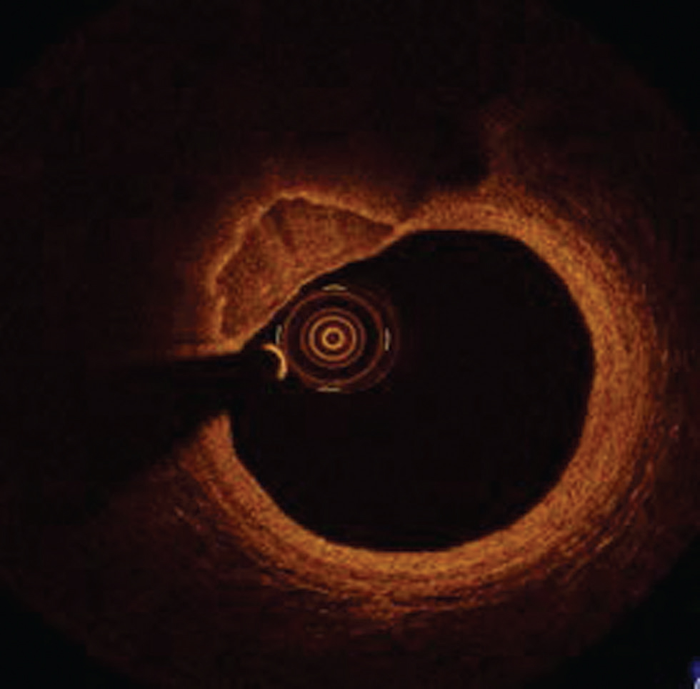
Calcified nodules show a highly calcified matrix causing substantial luminal irregularity with little or no lipid core.6 9 They are also prone to rupture and encountered 2 to 5% of sudden cardiac death cases and predominantly affect mid-right coronary artery (Fig. 7).
-
Fig. 7 Calcified nodule. Optimal coherence tomography image showing well-defined calcified nodule at 10 to 12 o’clock position.
Fig. 7 Calcified nodule. Optimal coherence tomography image showing well-defined calcified nodule at 10 to 12 o’clock position.
OCT in Vulnerable Plaque Assessment
High-resolution images of bright fibrous tissue obtained by OCT helps in inaccurate measurement of the thickness of fibrous cap in micrometers. Easy identification of lipid-laden plaque with a maximum lipid arc > 90° with thin fibrous cap (< 65µm) defines a thin cap atheroma as vulnerable plaque.10 A lipid-laden or lipid-rich plaque was defined as the plaque with lipid involving > 90°of the vessel wall circumference, that is, lipid arc.11 12
The lipid-core length is the length of plaque with > 90° of lipid arc and is measured on the longitudinal view. The lipid index is the lipid-core length multiplied by mean lipid arc.
Peculiar OCT Features in Female CAD
-
A) In ACS
-
Culprit vessel: Plaque morphology among males and females with ST-elevation myocardial infarction is similar. However, younger women presented more frequently with plaque erosions.
-
Nonculprit vessel: Women presented more frequently with nonobstructive coronary artery disease and microvascular dysfunction, causing greater morbidity and mortality. They also presented with greater visual–functional mismatch causing un-necessary PCI. Women also exhibited shorter lipid cores, smaller lipid index, and smaller lumen diameters compared with male counterparts.13
-
-
B) In stable coronary artery disease (CAD): Women with stable CAD had increased plaque vulnerability compared with men. Bharadwaj et al observed plaque rupture and thrombus in 10 and 8% females and 14 and 9% of males, respectively, in a series of patients with stable CAD.14
Clinical Utility of OCT Imaging
Clinical utility of OCT in the diagnosis of CAD is as follows:
-
Angiographically ambiguous lesions (e.g., dissection, thrombus, and calcified nodule).
-
To identify plaque morphology and determine the treatment options (medical management vs. PCI)
-
The periprocedural complication with stent implantation such as stent thrombosis, no-reflow.
-
For pre-procedural planning of complex bifurcation lesions.
Utility of OCT in Planning of PCI
The use of OCT should be considered for PCI planning and optimization in patients, especially with long lesions, left main (LM) lesions, thrombotic lesions, bifurcation lesions, and in calcified lesions.
-
1. OCT is used for the assessment of thickness and length of calcified plaque and can guide in lesson preparation.
-
2. In the selection of stent length and diameter—Based on currently available data from the ILUMIN III trial, the best approach for stent size selection by OCT is to use distal lumen reference and the EEL diameter.15 16 Subsequent dilatation of the proximal and mid part of the stent can be done to optimize stent expansion in these segments.
OCT can aid in stent length selection by identifying diseased segments and healthy landing zones. It helps in detecting edge dissection, malapposition, geographical misses, and so on, which can be a predictor of MACE.
3. Post-PCI stent optimization
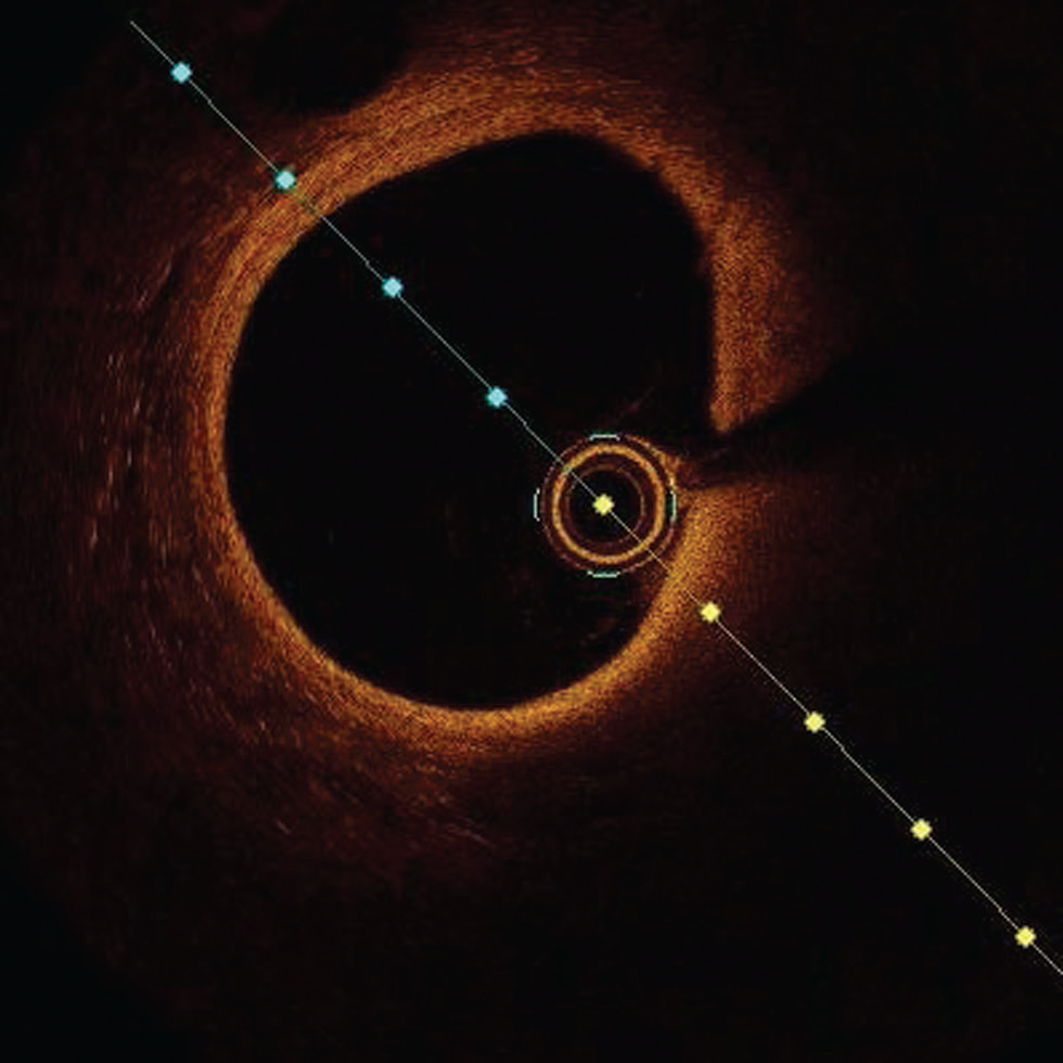
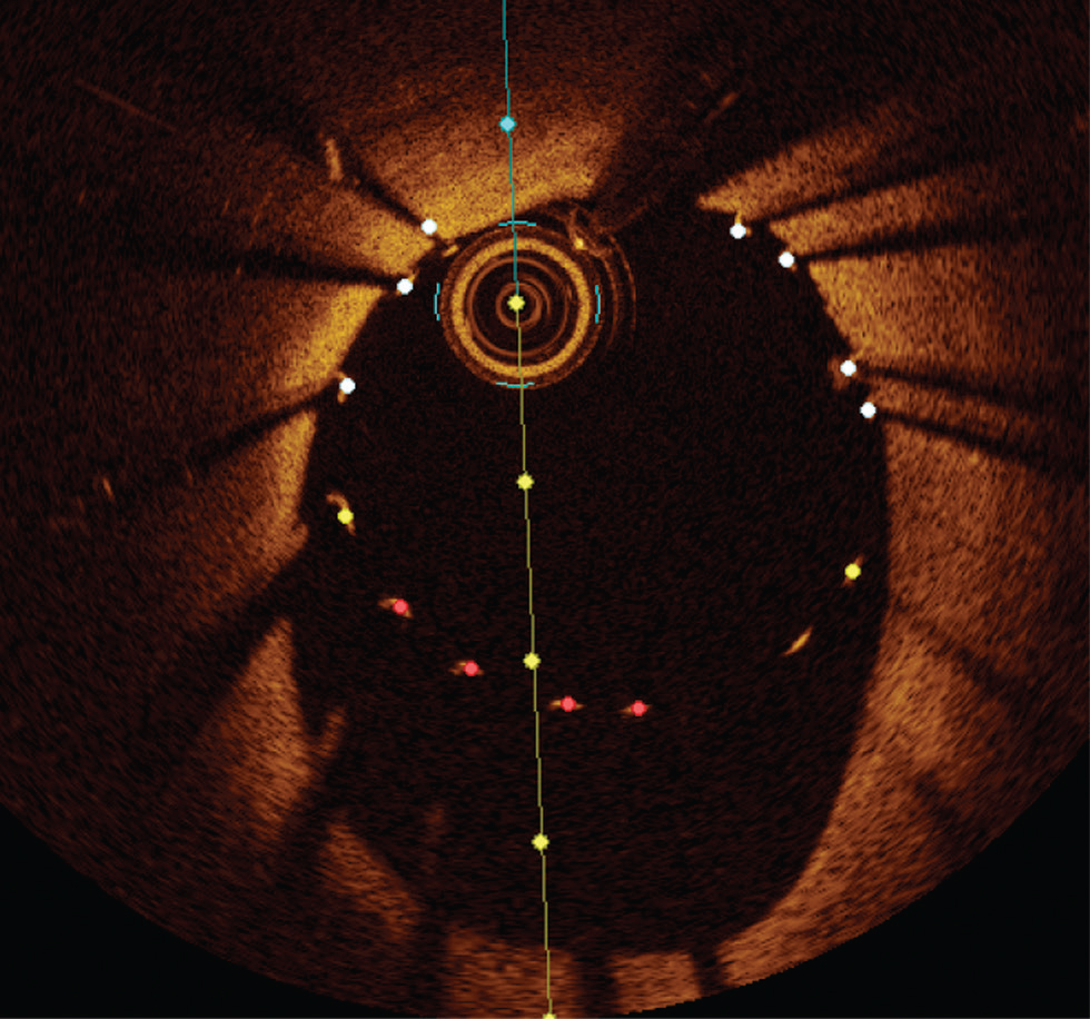
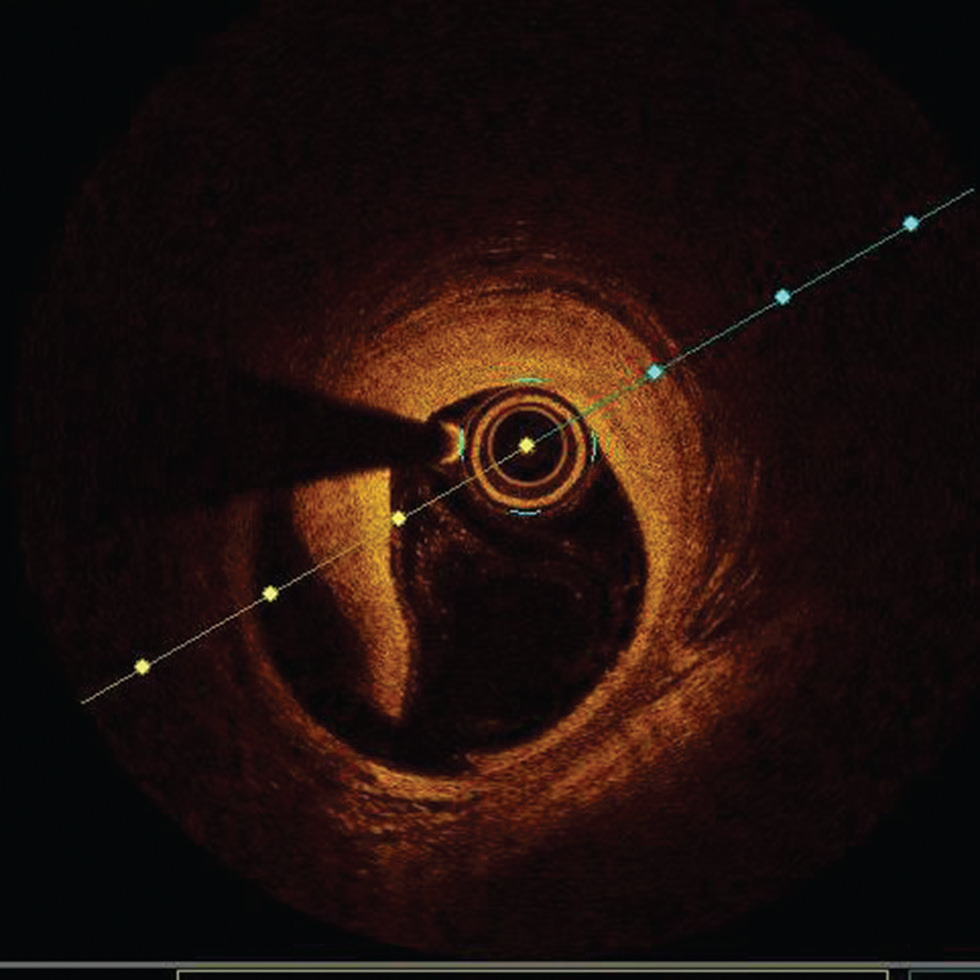
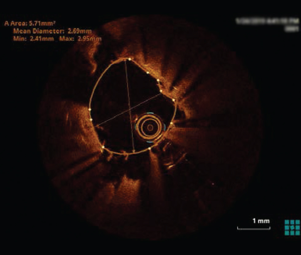
a. Stent under expansion—in general, greater achievable absolute stent expansion by OCT or IVUS results in improved long-term stent patency and better clinical outcomes. Available evidence would suggest that an absolute minimum stent area (MSA) of > 4.5 mm2 by OCT and relative MSA >80% of mean reference segment area should be considered as adequate stent expansion in non-LM lesions. However, these cutoffs cannot always be achieved in small vessels and can result in stent under-expansion in a large vessel. OCT angiography coregistration can help in accurate stent placement so as to avoid geographical misses. It avoids unnecessary postdilatation, thereby lowering the risk of edge dissection17 (Fig. 8).
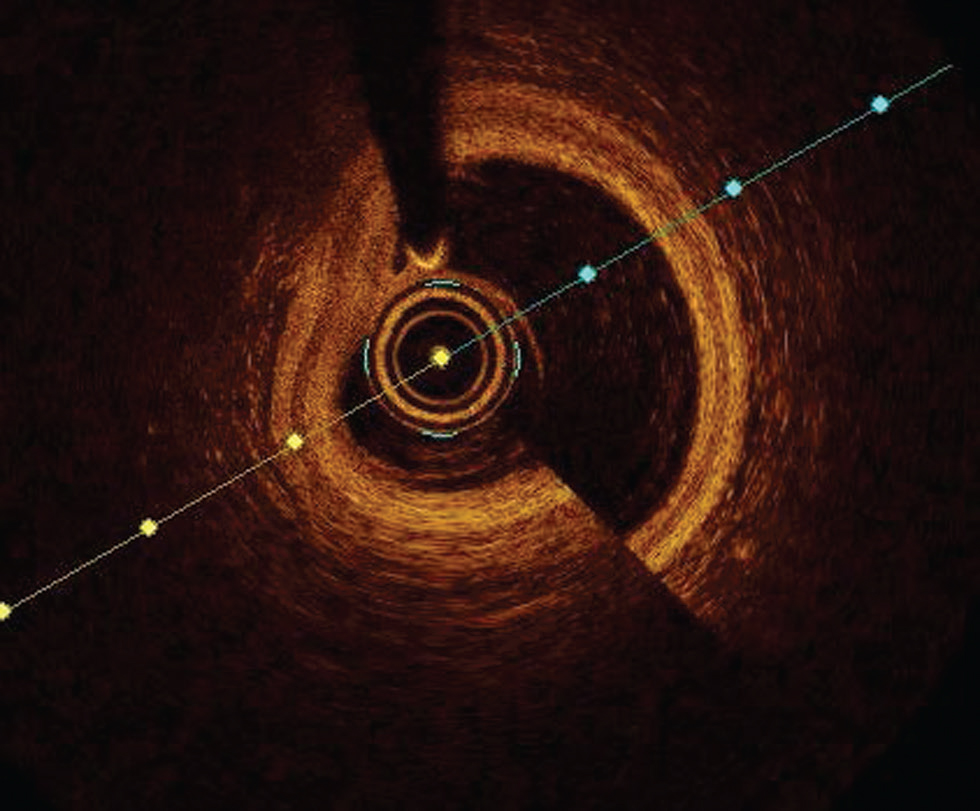
b. Stent malapposition or lack of contact of stent struts with vessel wall is commonly detected by OCT. OCT has better resolution than IVUS to measure accurately the axial distance of stents strut from the vessel wall (incomplete stent opposition distance) and its longitudinal extent. It is more common in the tortuous segment of the artery. Acute stent malapposition may be resolved by new intimal tissue growth if the ISA distance is < 0.4 mm, and the length is < 1 mm.18 Therefore, it is prudent to avoid extreme malapposition and correct it safely at the time of stent implantation when anatomically feasible (Fig. 9).
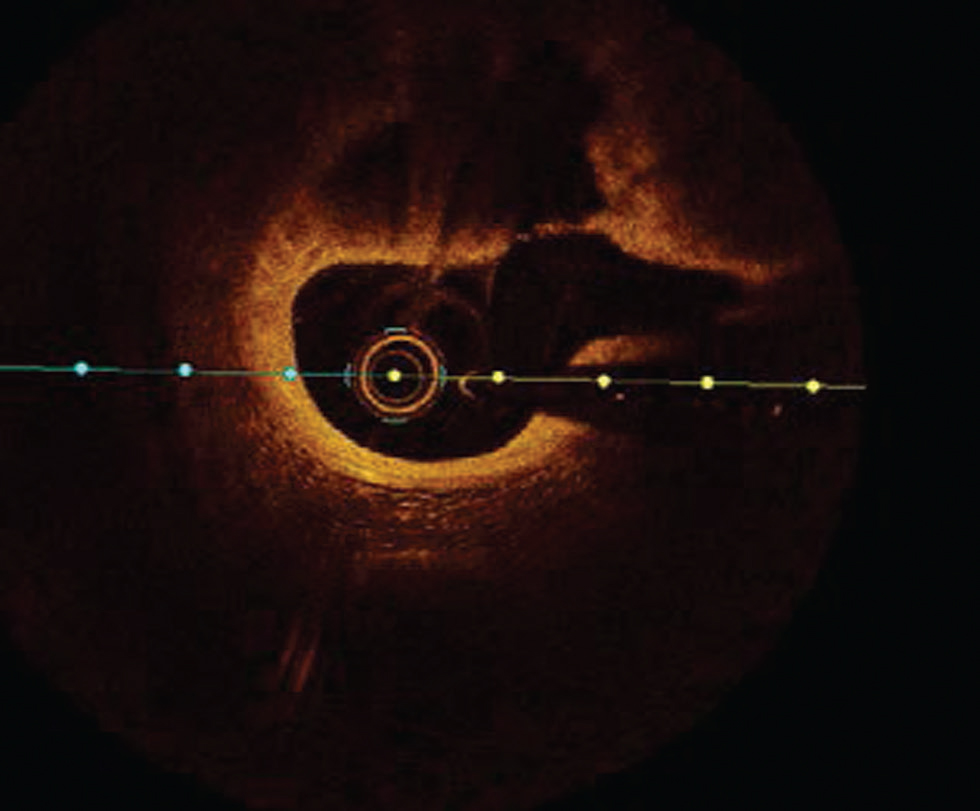
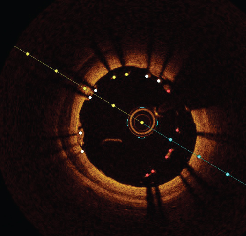
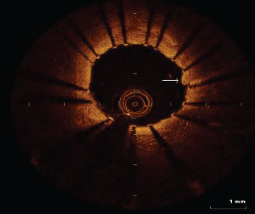
Tissue prolapse—OCT is superior in detection and identification of tissue characteristics of the material found protruding through stent struts into the lumen (tissue prolapse). It is more common in patients undergoing PCI for ACS with plaque rupture than plaque erosion or chronic stable plaques (Fig. 10).
c. Edge dissection—OCT due to its high resolution is ideal in identifying dissection. Based on randomized controlled trails and observational studies of routine OCT imaging, poststent implantation, minor edge dissection is very common. However, they do not portray adverse clinical outcomes and do not require routine additional intervention. In contrast, large edge dissection with > 60°arc > 2 mm length involving the medial or the distal edge should be treated with additional stenting.19 20 Identification of intramural or extramural hematoma at the stent edge by the OCT should be treated to reduce the acute stent thrombosis (Fig. 11)
-
Fig. 8 Undersized stent. Optimal coherence tomography image showing a huge gap between stent struts and luminal border s/o undersized stent.
Fig. 8 Undersized stent. Optimal coherence tomography image showing a huge gap between stent struts and luminal border s/o undersized stent.
-
Fig. 9 Stent malapposition. Optimal coherence tomography image showing lack of contact of stent struts with luminal border in most of the area.
Fig. 9 Stent malapposition. Optimal coherence tomography image showing lack of contact of stent struts with luminal border in most of the area.
-
Fig. 10 Tissue prolapse. The arrow shows tissue prolapse at 3 o'clock position.
Fig. 10 Tissue prolapse. The arrow shows tissue prolapse at 3 o'clock position.
-
Fig. 11 Edge dissection. Optimal coherence tomography image showing large edge dissection at 6 to 9 o'clock position.
Fig. 11 Edge dissection. Optimal coherence tomography image showing large edge dissection at 6 to 9 o'clock position.
Detection of Nonatherosclerotic Coronary Events (Fig. 12)
-
Fig. 12 Coronary arteritis. Optimal coherence tomography image shows irregularities in a luminal border in the case of coronary arteritis.
Fig. 12 Coronary arteritis. Optimal coherence tomography image shows irregularities in a luminal border in the case of coronary arteritis.
-
OCT can detect other nonatherosclerotic coronary events such as coronary arteritis.
-
It is a valuable tool to study evidence of coronary stent infection and arteritis.
Use of FFR along with OCT
Both fractional flow reserve (FFR) and OCT are used for functional assessment as well as post-percutaneous transluminal coronary angioplasty (PTCA) evaluation and optimization. In one of the recent trials, in intermediate coronary artery lesions, the use of FFR as compared with OCT leads to an increased rate of patients treated with medical therapy alone.21 Use of FFR for functional assessment of stenosis before PTCA and use of OCT for post-procedure optimization of results would be ideal.
Current Recommendations
OCT is used to access the mechanisms of stent failure—Class II a (level of evidence C)
OCT can be used in selective cases to optimize stent implantation—Class II, a (Level of evidence–C. (ESC2019).22
And according to ACC, the role of OCT in routine clinical decision making is not yet established.
Conclusion
OCT facilitates a customized outlook to PCI for patients with a higher risk of recurrence of ACS and stent failure. With further advances in technology, faster image acquisition, and more refined coregistered image analysis, OCT will be greatly adopted through the ease of use and interpretation.
Conflict of Interest
None declared.
References
- Assessing atherosclerotic plaque morphology: comparison of optical coherence tomography and high frequency intravascular ultrasound. Heart. 1997;77(05):397-403.
- [Google Scholar]
- The basics of intravascular optical coherence tomography. Postepy Kardiol Interwencyjnej. 2015;11(02):74-83.
- [Google Scholar]
- High-resolution coronary imaging by optical coherence tomography: feasibility, pitfalls and artefact analysis. Arch Cardiovasc Dis. 2010;103(04):215-226.
- [Google Scholar]
- Mechanisms of acute coronary syndromes and their implications for therapy. N Engl J Med. 2013;368(21):2004-2013.
- [Google Scholar]
- Lessons from sudden coronary death: a comprehensive morphological classification scheme for atherosclerotic lesions. Arterioscler Thromb Vasc Biol. 2000;20(05):1262-1275.
- [Google Scholar]
- In vivo diagnosis of plaque erosion and calcified nodule in patients with acute coronary syndrome by intravascular optical coherence tomography. J Am Coll Cardiol. 2013;62(19):1748-1758.
- [Google Scholar]
- EROSION Study (Effective Anti-Thrombotic Therapy Without Stenting: Intravascular Optical Coherence Tomography-Based Management in Plaque Erosion): a 1-year follow-up report. Circ Cardiovasc Interv. 2017;10(12):e005860.
- [Google Scholar]
- New morphological insights on coronary plaque rupture: bridging the gap from anatomy to clinical presentation? JACC Cardiovasc Interv. 2011;4(01):83-86.
- [Google Scholar]
- Coronary risk factors and plaque morphology in men with coronary disease who died suddenly. N Engl J Med. 1997;336(18):1276-1282.
- [Google Scholar]
- Frequency and spatial distribution of thin-cap fibroatheroma assessed by 3-vessel intravascular ultrasound and optical coherence tomography: an ex vivo validation and an initial in vivo feasibility study. Circ J. 2009;73(06):1086-1091.
- [Google Scholar]
- Characterization of human atherosclerosis by optical coherence tomography. Circulation. 2002;106(13):1640-1645.
- [Google Scholar]
- Sex-based differences in acute coronary syndromes: insights from invasive and noninvasive coronary technologies. JACC Cardiovasc Imaging. 2016;9(04):451-464.
- [Google Scholar]
- Multimodality intravascular imaging to evaluate sex differences in plaque morphology in stable CAD. JACC Cardiovasc Imaging. 2016;9(04):400-407.
- [Google Scholar]
- Optical coherence tomography compared with intravascular ultrasound and with angiography to guide coronary stent implantation (ILUMIEN III: OPTIMIZE PCI): a randomised controlled trial. Lancet. 2016;388:2618-2628. (10060)
- [Google Scholar]
- OCT compared with IVUS in a coronary lesion assessment: the OPUS-CLASS study. JACC Cardiovasc Imaging. 2013;6(10):1095-1104.
- [Google Scholar]
- Drug-eluting stenting: the case for post-dilation. JACC Cardiovasc Interv. 2008;1(01):22-31.
- [Google Scholar]
- Incomplete stent apposition and delayed tissue coverage are more frequent in drug-eluting stents implanted during primary percutaneous coronary intervention for ST-segment elevation myocardial infarction than in drug-eluting stents implanted for stable/unstable angina: insights from optical coherence tomography. JACC Cardiovasc Interv. 2009;2(05):445-452.
- [Google Scholar]
- Optical coherence tomography assessment of edge dissections after drug-eluting stent implantation in coronary artery. Chin Med J (Engl). 2012;125(06):1047-1050.
- [Google Scholar]
- Incidence, predictors, morphological characteristics, and clinical outcomes of stent edge dissections detected by optical coherence tomography. JACC Cardiovasc Interv. 2013;6(08):800-813.
- [Google Scholar]
- Prospective randomized comparison of fractional flow reserve versus optical coherence tomography to guide revascularization of intermediate coronary stenoses: one-month results. J Am Heart Assoc. 2019;8(15):e012772.
- [Google Scholar]
- Optical coherence tomography to optimize results of percutaneous coronary intervention in patients with non-ST-elevation acute coronary syndrome: results of the multicenter, randomized DOCTORS study (Does Optical Coherence Tomography Optimize Results of Stenting). Circulation. 2016;134(13):906-917.
- [Google Scholar]