

Translate this page into:
Intravascular Ultrasound
Lalita Nemani, MD, DM, FESC Department of Cardiology, Nizam’s Institute of Medical Sciences Hyderabad India drlalita775@gmail.com
This article was originally published by Thieme Medical and Scientific Publishers Private Ltd. and was migrated to Scientific Scholar after the change of Publisher.
Introduction
Percutaneous coronary intervention (PCI) has witnessed phenomenal technological leaps during the last decade. Along with improved hardware and better stent design, the advent of intravascular imaging has made dynamic improvements in both short-term and long-term outcomes following PCI. Intravascular imaging has also helped refine our understanding of the mechanisms and pathophysiology of coronary syndromes, the morphology of atherosclerotic plaques, and the factors responsible for less than optimal outcomes following intervention in the form of stent thrombosis and stent restenosis.
Intravascular imaging has also proved invaluable in left main coronary artery (LMCA) interventions, and bifurcation lesions, where achieving a predefined optimal result has implications for survival and outcomes to match the results of coronary artery bypass grafting (CABG).1 Intravascular ultrasound (IVUS) has also helped optimize PCI in conditions like a renal compromise by limiting the contrast use.
Principles of IVUS
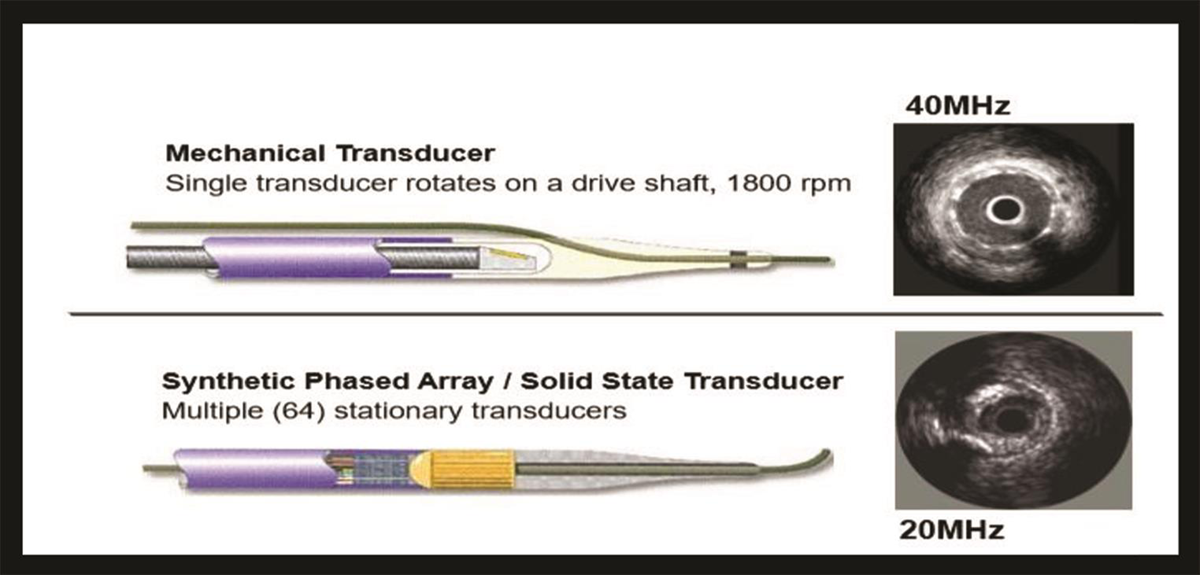
Ultrasound images are produced by passing an electrical current through a miniature transducer incorporated near the tip in specialized catheters. The transducer contains piezoelectric crystals (usually ceramic) that expand and contract when electrically excited to produce sound waves. Ultrasound is reflected at interfaces between tissues or structures of different density. After reflection from tissue, ultrasound waves return to the same transducer to create an electrical impulse that is then converted into the image. The IVUS gray scale image is derived from the amplitude of the reflected signal, but not from the frequency of the reflected signal. A white image means that more of the signal is reflected, and the amplitude is greater; a black image means that less of the signal is reflected, and the amplitude is less.2 A central frequency increases the axillatory frequency increases, but penetration ability comes down. In coronary imaging, as the transducer is close to the vessel wall, high frequencies (20–40 MHz) ultrasound waves are utilized. This provides an axial resolution of 80 to 120 µm and a lateral resolution of 200 to 500µm.
Two companies are providing IVUS machine—Philips Healthcare (Eagles Eye Platinum, Revolution 45 MHz rotational, Refinity short tip rotational [Boston Scientific Gesells chaft GmbH, Austria, Vienna]) and Boston Scientific ( OptiCross [Philips Medical Systems, Los Angeles, United states]).
Before starting the IVUS imaging to prevent coronary spasm, 100 to 200 µg of nitroglycerin intracoronarlly is advisable to be given.
IVUS Equipment
IVUS catheters: Presently available catheters are rapid exchange monorail catheters. The outer diameter is 2.6 to 3.5 Fr (0.87–1.17 mm) and can be advanced through a 6-French guide catheter.
The transducer system is two types: mechanical system and electronic system. Comparisons and differences of these systems are mentions in Tables 1 2 Fig. 1.
|
Mechanical IVUS system |
Electronic or solid-state system |
|---|---|
|
|
|
Properties and use |
IVUS (40–45 MHz) |
IVUS (50–60 MHz) |
|---|---|---|
|
Wave source |
Ultrasound |
Ultrasound |
|
Axial resolution, µm |
38–46 |
20–40 |
|
Penetration depth in soft issue, mm |
>5 |
3–8 |
|
Distance between adjacent frames, mm |
0.02–0.03 |
0.02–0.17 |
|
Maximum pullback |
100–150 |
100–150 |
|
Blood issue |
Moderate backscatter from blood |
Strong backscatter from blood |
|
Aorto-ostial lesion visualization |
+ |
+ |
|
Cross-sectional calcium evaluation |
Angle only |
Angle only |
|
Lipidic plaque evaluation |
Attenuated plaque |
Attenuated plaque |
|
Plaque burden at lesion site |
+ |
+ |
-
Fig. 1 Images of mechanical and solid-state transducers.
Fig. 1 Images of mechanical and solid-state transducers.
Imaging console: The console has a soft way to convert the IVUS signal to an image. The image is displayed on the monitor and can be recorded digitally. Currently, three display modes are available.
1. Cross-sectional tomographic view gives information about the space orientation but cannot give the information about the plaque burden and length of the lesion; It is present in all present-standard IVUS systems.
2. Longitudinal imaging (L mode) It is a constructed image displaying the longitudinal appearance of the artery. Useful for lengths measurements and interpolation of shadowed deep arterial structures (i.e., external elastic membrane behind calcium or stent metal). A single cut plane is a limitation other than straight reconstruction of the artery. L mode generation requires motorized pullback and digital storage of cross-sectional images. Feasible in present-day IVUS systems.
3. Three-dimensional reconstruction images are still in the research phase; the process requires registration of catheter path during pullback.
Both manual and motorized pullback techniques are available with advantages and disadvantages. Whenever feasible, the motorized pullback is usually preferable as it allows accurate assessment of length and volumes, and image acquisition is consistent and reproducible.
Imaging artifacts: Due to these artifacts, image interpretation becomes difficult. These are ring-down artifacts, reverberations, side lobes, ghost artifacts (which can happen in any ultrasound machine like two-dimensional echocardiogram), saw tooth appearance, and axial motion artifact.
-
Ring down artifacts are common with phased array systems. These appear as parallel bands or haloes surrounding the catheter and obscure the near field imaging. This can be minimized by pressing ring down button before imaging the coronaries.
-
Reverberations Echo reflectors like stents, wires, and calcium produces acoustic noise and pulse reverberations.
-
Side lobes and ghost artifacts Like reverberations, these are also produced by strong echo reflectors.
-
Saw tooth appearance On L mode, catheter pullback produces the catheter motion as saw tooth appearance.
-
Artifact due to catheter position: Off-axis position shows vessel geometry in the elliptical position, leading to overestimation of the luminal area.
-
Axial motion artifact: Retrograde and antegrade movement of IVUS produces blurred images, which decreases the quality of three-dimensional reconstructive images.
Normal Appearance of a Vessel Wall on IVUS
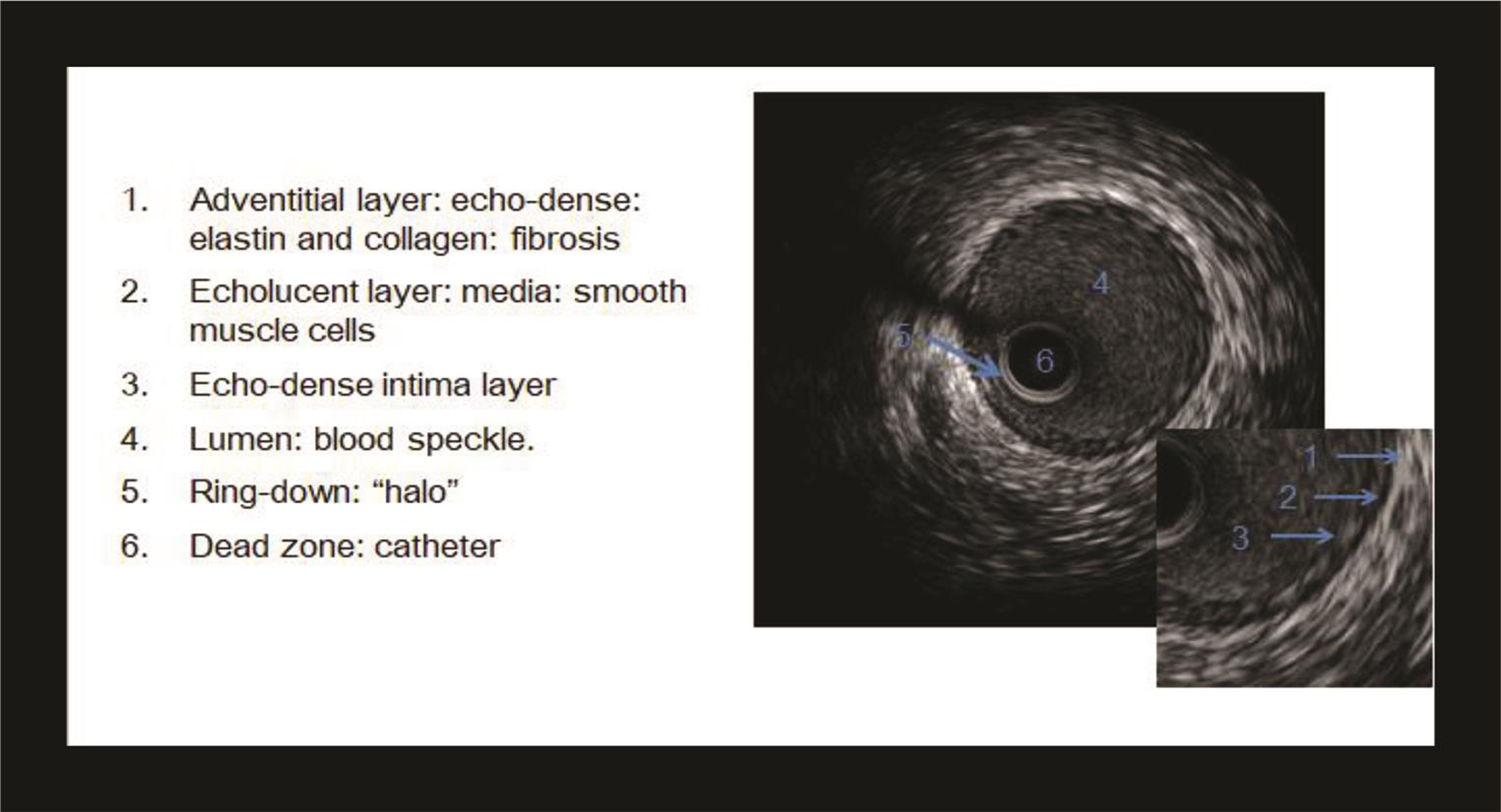
A typical IVUS image consists of three parts—the catheter, lumen, and vessel wall (Fig. 2). The lumen is recognized by the presence of blood speckle, that is, finely textured swirling echoes arising from the blood components.
-
Fig. 2 Normal artery demonstrating all three layers of the vessel wall.
Fig. 2 Normal artery demonstrating all three layers of the vessel wall.
Normal coronary artery on IVUS appears trilaminar displaying intima as bright echo, media as dark, and adventitia again as bright.
Intima The innermost layer intima is relatively echogenic and appearance as a single bright concentric echo. Normal intimal thickness increases with age, and an intimal thickness <300 µm (0.3 mm) is considered normal in an adult younger than 40 years and <500 µm in adults older than 40 years.
Media Media appears dark due to low ultrasound reflectance owing to homogeneous smooth muscle distribution and smaller quantities of collagen, elastic tissue, and proteoglycans. Normal medial thickness averages 200 µm; however, thinning is seen in atherosclerosis. In advanced atherosclerosis, the media may not appear intact circumferentially. The thickness of the media is inversely related to the thickness of the lesion.
Adventitia The outermost adventitia is composed of collagen and elastic tissue and appears bright. Normal adventitia measures 300 to 500 µm in thickness.
The intima–media, that is, the internal elastic membrane, is poorly defined as the intima layer reflects ultrasound more than media.
The external elastic membrane (EEM), that is, the media–adventitia border, is accurately defined due to step up in echo-reflectivity.
The outer most border of adventitia is indistinct due to echo-reflectivity like surrounding peradventitial tissues.
The normal coronary artery in the young may appear monolayer due to the presence of a very thin intimal layer, that is, <100µm.
IVUS Examination Technique
The IVUS catheter is passed intracoronary distal to the segment of interest (at least 10 cm of distal reference) through the standard angioplasty guide catheter and 0.014-inch coronary angioplasty guidewire. The operator pulls back the transducer either manually (0.5 mm/sec) or motorized (constant speed of 0.25–1 mm/sec usually 0.5 mm/sec). During pullback, images are obtained and recorded digitally for analysis.
Image Interpretation on IVUS
-
Atherosclerotic plaque: Three types of plaque depending on the echogenicity, which is taken in relation to adventitia as standard.
-
Thrombus: Appears as relatively echo lucent mass within the lumen, blood flow through microchannels may be visible within the mass. IVUS is only 57% sensitive and 91% specific for detection of thrombus. It is difficult to differentiate thrombi from soft plaque, loose connective tissue, and slow flowing or stagnant blood.
-
Dissection: Recognized by the presence of intimal flap, false lumen, or a second blood-filled channel. IVUS is sensitive to the detection of coronary dissection. Injection of contrast will show the connection between true and false lumen. A spontaneous dissection appears as a medial dissection with an intramural hematoma (Fig. 5).
-
Hematoma: An intramural hematoma appears as dark spaces within the adventitia. When large, it usually displaces the internal elastic membrane inwards and external elastic membrane outwards.
-
Plaque rupture and ulceration: Appears as a cavity in the vessel wall with intimal disruption and blood with the cavity.
-
Coronary aneurysm: When the EEM and lumen diameter is >50% than that of the proximal reference segment, an aneurysm is to be considered. IVUS can discriminate between a true aneurysm and a pseudoaneurysm.
-
Intimal hyperplasia: Characterized by both cell proliferation and extracellular matrix accumulation and contributes to in-stent restenosis. Appears as low echogenic in early ISR while more echogenic in late ISR.
-
Arterial remodeling: Refers to changes in the area of the EEM that occurs during atherosclerosis. It is frequently expressed as a ratio of lesion EEM cross-sectional area (CSA) to reference EEM CSA. The reference site is taken within 10 mm from the lesion.
-
Positive remodeling is also known as outward or expansive remodeling. This refers to an increase in arterial dimensions. It is seen in the early stages of atherosclerosis.
-
Negative remodeling is also known as inward or constrictive remodeling. This refers to a smaller arterial dimension. The absolute reduction in lumen dimensions is seen when the plaque burden is 40 to 50% or more. Negative remodeling can explain angiocardiographically looking stenosis without a plaque.
-
-
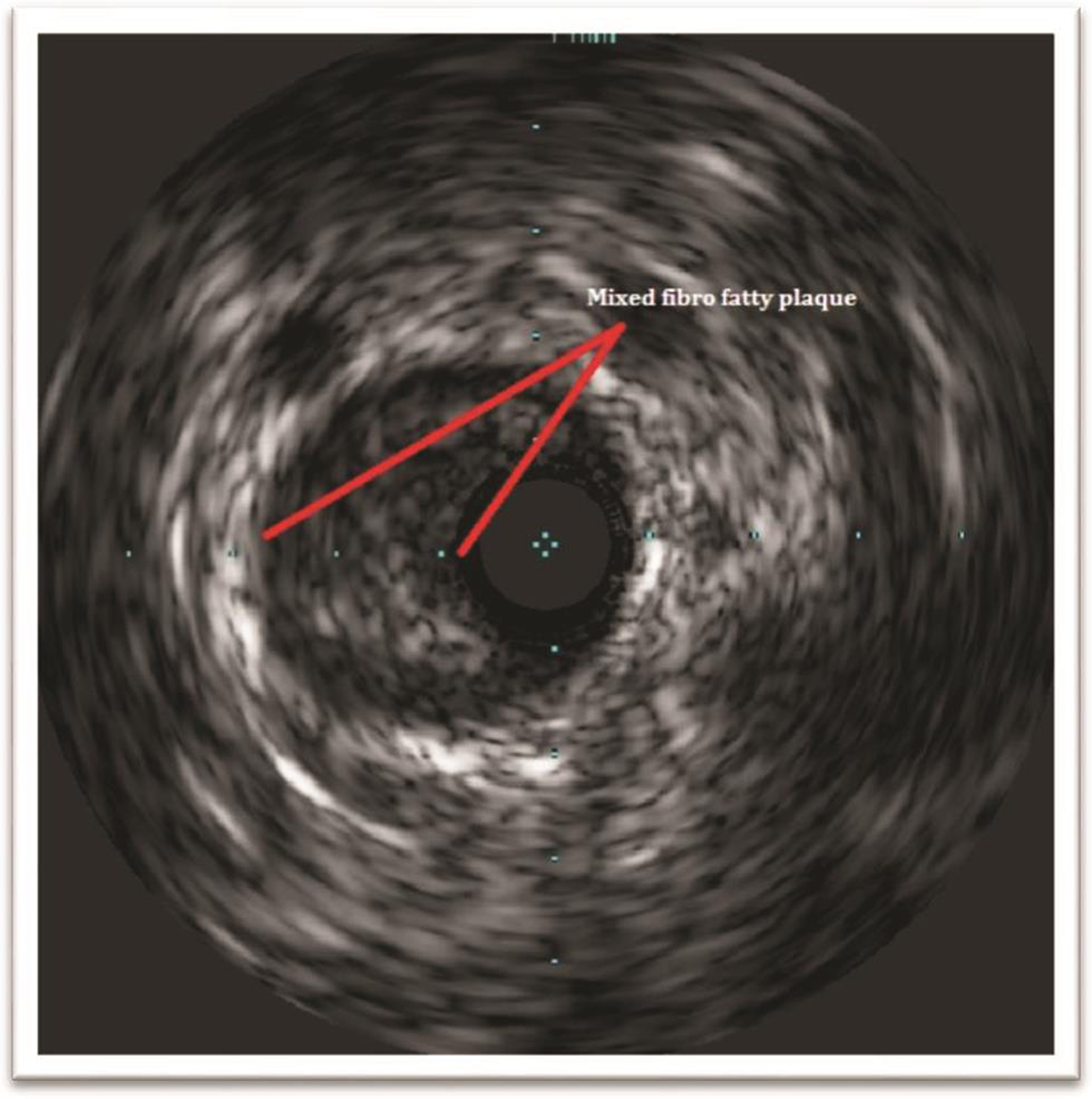
Fig. 3 IVUS image of fibrofatty eccentric plaque.
Fig. 3 IVUS image of fibrofatty eccentric plaque.

-
Fig. 4 IVUS images showing intimal calcific of plaque.
Fig. 4 IVUS images showing intimal calcific of plaque.

-
Fig. 5 Different pathologies on IVUS.
Fig. 5 Different pathologies on IVUS.
Various Definitions of Arterial Remodeling
-
Calculation of the arterial remodeling = EEM CSA at lesion/average of the proximal + distal reference EEM CSA
Positive remodeling is an index >1.0.
Negative remodeling <1.0.
-
Second definition:
Positive remodeling: lesion EEM > proximal reference EEM
Intermediate remodeling: lesion EEM between the proximal and distal reference EEM
Negative remodeling: lesion EEM < distal reference EEM.
-
Remodeling index = lesion EEM/reference EEM
Positive remodeling = index >1.05
Intermediate remodeling = index of 0.95–1.05
Negative remodeling= index <0.95
In a prospective study, Inaba et al showed the effect of remodeling to predict the MACE.4
IVUS Measurements
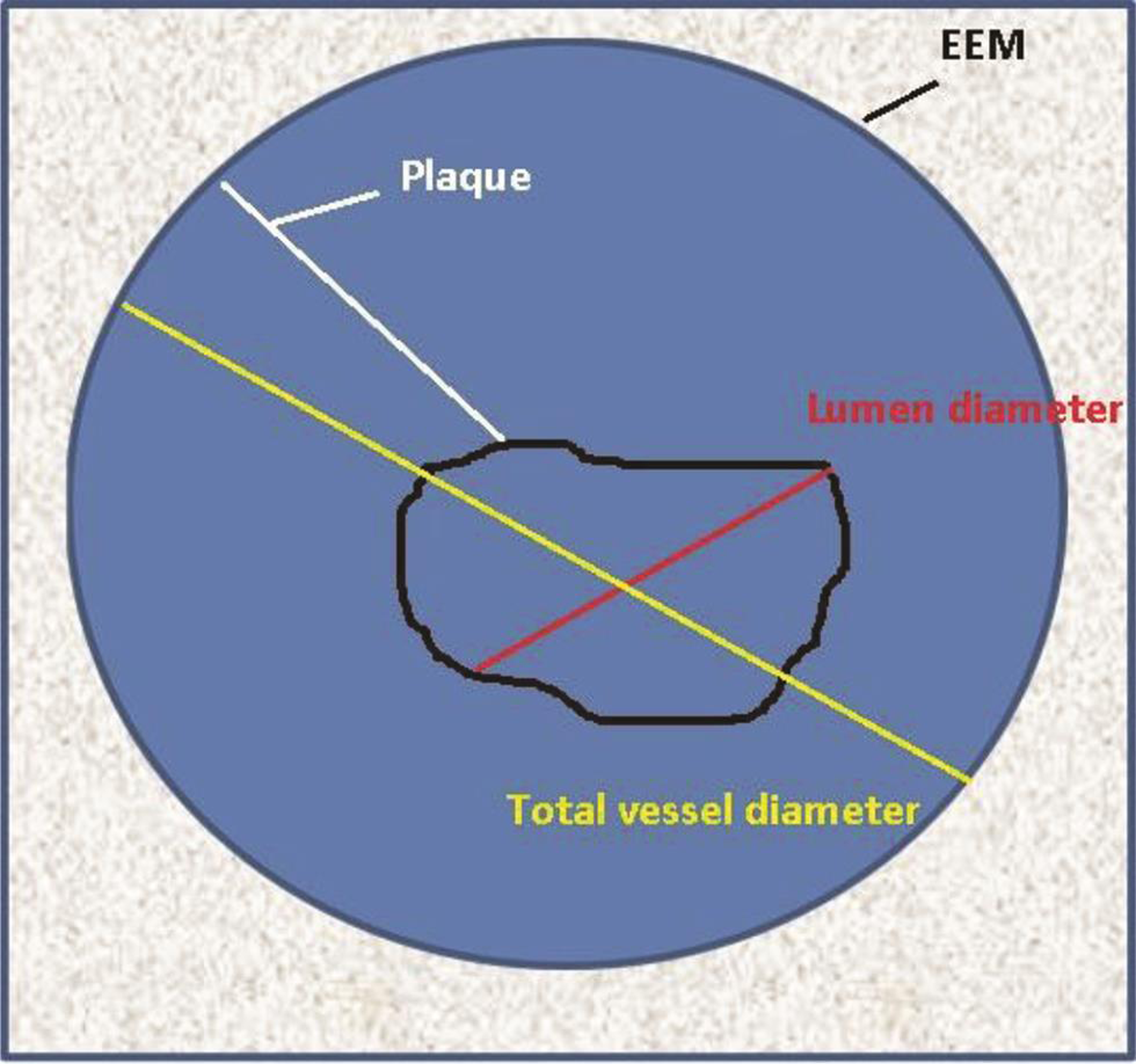
The center of the vessel lumen is the reference point for all measurements. The borders can be either delineated manually or automatic correction for calculations of various distances and areas (Table 3 Fig. 6).
|
Basic measurements |
Definition and calculations |
|---|---|
|
Lumen CSA |
The area bounded by the luminal border |
|
Minimum lumen diameter |
Shortest diameter through the center of the lumen |
|
Maximum lumen diameter |
Longest diameter through the center of the lumen |
|
Lumen eccentricity |
100 × (maximum lumen diameter − minimum lumen diameter/maximum lumen diameter |
|
Lumen area stenosis |
Reference lumen CSA − minimum lumen CSA/reference lumen CSA. Like angiographic percentage stenosis. |
|
EEM CSA |
The area bordered by the EEM |
|
Plaque area |
EEM CSA − lumen CSA |
|
Plaque burden |
Plaque CSA/EEM CSA |
|
Plaque eccentricity |
100 × (maximum plaque thickness − minimum plaque thickness/maximum plaque thickness |
|
Intimal hyperplasia |
Stent CSA − lumen CSA |
|
Arc of calcium |
Degree of the circumference of calcification |
-
Fig. 6 Diagrammatic representation of IVUS image demonstrating different IVUS measurements.
Fig. 6 Diagrammatic representation of IVUS image demonstrating different IVUS measurements.
Virtual Histology on IVUS
Virtual histology (VH) on IVUS helps to know the plaque composition. The images are acquired from the ultrasound signals having a different radiofrequency spectrum, which will be displayed in different colors. This color-coded map is overlapped on the grayscale image of the IVUS.VH-IVUS data are collected with a 20-MHz, 2.9-Fr phased-array transducer catheter (Eagle Eye TM Gold, Volcano Therapeutics, Rancho Cordova, California, United States) that acquires IVUS data that are ECG-gated (Fig. 7a b).

-
Fig. 7 Virtual histology of fibrofatty lesion. (a) Cross-sectional and longitudinal sections. (b) Colorized tissue map.
Fig. 7 Virtual histology of fibrofatty lesion. (a) Cross-sectional and longitudinal sections. (b) Colorized tissue map.
In VH-IVUS, four basic tissue types constitute the plaque composition:
-
Green—fibrous tissue
-
Light green—fibrofatty tissue
-
Red—necrotic tissue
-
White—dense calcium
The lesions are classified as pathologic intimal thickening (PIT), fibrotic, fibrocalcific, thick-cap fibro atheroma (ThFA), or thin-cap fibro atheroma (TCFA) (Fig. 8).

-
Fig. 8 Virtual histology by IVUS showing different types of plaque morphologies
Fig. 8 Virtual histology by IVUS showing different types of plaque morphologies
VH enables detected of vulnerable plaque before rupture. It has a predictive accuracy of 90.4% for fibrous tissue, 92.8% for fibrolipidic, 89.5% for necrotic core, and 90.9% for dense calcium. However, the clinical implication of this is still not clear.
The PROSPECT study demonstrated that MACE was related to plaque burden (≥ 70%, MLA of ≤4.0 mm2) and the presence of thin fibrous CAP atheroma.4 VIVA study, plaque burden >70%, and TCFA on VH were associated with major cardiac events (MACE).5
iMAP software and integrated backscatter analysis (IB) are two other tissue classification scheme based on radiofrequency analysis of the reflected ultrasound signal.
IVUS in Clinical Practice
Intermediate Coronary Lesion
Coronary angiography appears ambiguous in arteries with a 40 to 70% plaque burden, frequently underestimating the severity. FFR is a well-established physiological index to assess the functional significance of a stenosis. Many studies have reported a correlation between FFR values and IVUS derived measurements of which minimum lumen area (MLA) cutoff values have been near ideal. MLA of 2 to 3.9 mm2 in non–left main artery (non-LMCA) lesion and 4.5 to 5.9 mm2 in LMCA lesion correlated with ischemic FFR in different studies.
-
First study (fractional flow reserve and intravascular ultrasound relationship): MLA of 3.02 mm2 best cut off for ischemia.
-
Hans et al: MLA of 2.75 mm2 as best cutoff for FFR <0.8. On subgroup analysis, it is 2.75 mm2 for Asians and 3.0 mm2 for Westerners.
-
A meta-analysis showed that different cutoff points for IVUS-MLA for the severity of the stenosis (for LMCA 5.35 mm2 and non-LMCA 2.61 mm2).
IVUS studies show a higher negative predictive value (77–96%) and a low positive predictive value (39–73%) of MLA for ischemia prediction. IVUS should be used to defer PCI depending upon the vessel size, but IVUS should not be used to perform the intervention.
LMCA Interventions
LMCA disease is frequently underestimated by conventional coronary angiogram. In fact a very high percentage of patients with normal-looking left main on angiography have a disease on IVUS. Conversely, in ostial lesions, only half of the angiographically ambiguous LMCA has significant disease. To decide the actual size of the MLA of LMCA, it is recommended to have a pullback from both left anterior descending artery (LAD), left circumflex artery (LCX), to LMCA.
Utility of IVUS in PCI Optimization
-
Preintervention: IVUS is performed to assess the severity of stenosis, plaque composition and distribution, reference vessel size, and lesion length. As a result, stent size and length can be chosen more accurately than on angiography. Stent size in the traditional method is selected by identifying the maximum reference lumen diameter (either proximal or distal whichever is the larger). In a remodeled vessel 80% of the average (distal and proximal) reference vessel diameter is taken as appropriate stent size. The mid-wall calculation method is applicable in remodeled vessel which is calculated as half of the combined distal reference vessel and lumen diameter. In aggressive IVUS method for stent sizing, the average of the orthogonal distance from the media to the media is taken, but this proved to be oversizes the stent. Another method of calculation for stent size is to take average of diagonal distance between media to media and intima to intima. The optimal proximal and distal landing zone are identified as the site of the largest lumen with minimum plaque burden ideally <50%. Stent length can be estimated only on motorized transducer pullback as the distance between the proximal and distal landing zones. IVUS also is useful in deciding whether the aorto-ostial junction is to be stented in the case of LMCA or proximal RCA lesion. Ideally, the aorto-ostial junction is to be stented if the plaque burden is >50%.
Stents can be sized either to the true vessel size, or media to media, or mid-wall dimensions. Usually, media to media is considered and the stent is downsized by 0.5 mm.
-
Postintervention: IVUS helps in identifying predictors of early stent thrombosis and/or in-stent restenosis such as stent under expansion, plaque prolapse, significant dissections, edge plaque burden, or edge stenosis and geographical miss (Fig. 9).8 9
-
Stent under expansion
When balloon angioplasty was introduced, the increase in the lumen size was thought to be because of plaque compression, but IVUS studies demonstrated that luminal enlargement is due to plaque distribution and vessel expansion. That’s why even properly expanded stent also shows significant plaque beyond the stent on the IVUS examination (Fig. 10).
In the multicenter ultrasound stenting in coronaries study (MUSIC) criteria, “adequate” expansion was defined as >90% of the average reference cross-sectional area (CSA) or >100% of a smaller reference CSA with complete apposition and symmetric expansion. Another large multicenter trial was AVID (angiographic versus IVUS direct stent placement); its defined IVUS optimization required complete stent apposition with stent CSA >90% of the distal reference lumen area.10 11
b. Stent mal apposition: Apposition refers to contact between the stent struts and the arterial wall. Mal apposition is defined as one or more struts clearly separated from the vessel wall with evidence of blood speckles behind the struts (Fig. 11). Acute stent mal-apposition is not a predictor of stent thrombosis is the stent is well expanded.
Criteria for optimal PCI by IVUS: A well-expanded stent with no gap between the struts and vessel wall, no atheroma or dissection at the edge is the optimal PCI result craved for (Figs. 12 13).
c. Identification of complications: IVUS is more sensitive than angiography in detecting complications.
-
Dissection: Dissection is seen as separation either in the plaque or in the intima. Dissection may be confined to intima or may extend into media or even to the adventitia. It may be focal produced conferential lesion or long, producing a longitudinal dissection. If MLA after dissection is <4 mm2 or dissection angle >60°, then chances of developing stent thrombosis is high (Fig. 14). The majority of minor edge dissections need not be treated and are found to have healed when imaged at follow-up. Dissection may be missed on IVUS is the vessel lumen is severely stenosed, or the catheter closes the flap or if the dissection is behind a calcified plaque.
-
Intramural hematoma: It is a variant of dissection where blood accumulates in the medial space. The EEM bulges out, and internal elastic membrane encroaches to compromise the lumen. Typically appear hyperechoic and crescent shaped.
-
Coronary perforation and rupture: Could be guidewire/balloon or stent induced. Three distinct patterns are described in IVUS.
-
Free blood speckle outside EEM
-
Extramural hematoma—accumulation of blood outside EEM
-
Peradventitial echolucency suggesting extravasation
-

-
Fig. 9 IVUS for post percutaneous coronary intervention (PCI).
Fig. 9 IVUS for post percutaneous coronary intervention (PCI).

-
Fig. 10 IVUS image of the stent under expansion(a) focal and (b) diffuse.
Fig. 10 IVUS image of the stent under expansion(a) focal and (b) diffuse.

-
Fig. 11 IVUS figure of stent malapposition.
Fig. 11 IVUS figure of stent malapposition.

-
Fig. 12 Flow chart for optimization of the stent by IVUS (courtesy of AVIO study authors)12
Fig. 12 Flow chart for optimization of the stent by IVUS (courtesy of AVIO study authors)12

-
Fig. 13 Criteria for optimal percutaneous coronary intervention (PCI) by IVUS
Fig. 13 Criteria for optimal percutaneous coronary intervention (PCI) by IVUS

-
Fig. 14 IVUS images showing the different extent of the dissection.
Fig. 14 IVUS images showing the different extent of the dissection.
Role of IVUS in Restenosis
IVUS studies showed that negative arterial remodeling is the cause of restenosis in nonstented vessels, whereas neointimal hyperplasia but not the chronic stent recoil is responsible for in-stent restenosis.
-
Stent under expansion is the most common cause for restenosis—this is due to poor expansion and not chronic recoil of the stent (Fig. 15).
Other mechanical and technical causes for restenosis seen in 4.5% cases are as follows:
-
Missing the lesion (e.g., aorto-ostial stenosis).
-
Stent “crush.”
-
Sent stripped off the balloon during the implantation.
-
Stent strut fracture.
-
Late stent malapposition (LSM) results from regional vessel positive remodeling, and may not contribute to MACE, though some cases of late stent thrombosis have been reported.

-
Fig. 15 Minimal stent area cutoff values for the prediction of ISR on a segmental basis13
Fig. 15 Minimal stent area cutoff values for the prediction of ISR on a segmental basis13
IVUS Findings in Unstable Lesions
-
Culprit lesions in ACS have large plaque area and show positive remodeling.
-
Echo-lucent plaques are common.
-
Unstable lesions have less calcium which is usually small, focal, and deep.
Typical IVUS features in acute myocardial infarction are as follows:
-
Plaque rupture
-
Thrombus
-
Positive remodeling
-
Attenuated plaque
-
Spotty calcification
-
Thin cap fibroatheroma
Attenuated plaque is hypoechoic or mixed atheroma without calcification or very dense fibrous plaque. Histopathologically, they denote fibro atheroma with necrotic core and a lipid intimal thickening.
IVUS in CTO Lesions
IVUS is helpful in chronic total occlusions (CTO) management at multiple places.14
-
In ambiguous proximal occlusion cap—IVUS helps to determine the optimal entry point and evaluate guidewire penetration of the proximal cap of a CTO.
-
IVUS of the side branch at the occlusion site allows the cross-sectional image of the proximal cap and central lumen of the CTO.
-
The precise location of the guidewires within an artery (i.e., true lumen versus subintimal) after crossing the lesion.
-
Even when the wire is in subintimal space, IVUS will show the direction of the true lumen, so that with another wire under IVUS guidance true penetration can be done.
-
It is also particularly useful in complex CTO procedures when the course or position of the retrograde wire has to be identified.
-
IVUS in antegrade subintimal space, to guide the retrograde wire manipulations to enter the true lumen.
-
After opening the occluded artery, the final dimension of the vessel to determine the stent size.
IVUS in Cardiac Allograft Vasculopathy
IVUS is used at 4 - 6 weeks after the heart transplantation to exclude the donor CAD. IVUS study at one year is useful for prognostication and to detect the rapidly progressive cardiac allograft vasculopathy (CAV) (AHA/ACC class IIa indication).
Outcomes by IVUS
A meta-analysis of IVUS studies showed that IVUS-guided PCI is associated with a reduction of MACE by 41%, mortality by 54%, stent thrombosis by 51%, and ischemia driven revascularization by 40% in newer studies, whereas older studies of IVUS demonstrated the feasibility and superiority of IVUS over angio-guided PCI (Tables 4 5).15 16 17 18 19 20
|
References |
Year |
RCT |
Non-RCT |
Pts. |
MACE |
Death |
MI |
ST |
Target lesion revascularization |
Target vessel revisualization |
|---|---|---|---|---|---|---|---|---|---|---|
|
Abbreviations: PCI, percutaneous coronary intervention; RCT, randomized control trials; MACE, major adverse cardiac events; MI, myocardial infarction; NS, statistically not significant; S, statistically significant. |
||||||||||
|
Zhang et al (Euro intervention)15 |
2012 |
1 |
10 |
19,619 |
S |
S |
NS |
S |
NS |
NS |
|
Propensity score-matched sub-analysis |
5,300 |
NS |
S |
S |
S |
NS |
NS |
|||
|
Klersy et al16 |
2013 |
3 |
9 |
18,707 |
S |
S |
S |
NS |
NS |
|
|
Jang JS et al17 |
2014 |
3 |
12 |
24,869 |
S |
S |
NS |
NS |
NS |
NS |
|
Propensity score-matched sub-analysis |
13,545 |
S |
S |
NS |
NS |
NS |
NS |
|||
|
Ahn et al18 |
2014 |
3 |
14 |
26,503 |
S |
NS |
NS |
NS |
NS |
NS |
|
Zhang et al (BMC cardiovascular disorder)19 |
2015 |
3 |
17 |
29,068 |
S |
NS |
NS |
NS |
NS |
NS |
|
Propensity score-matched sub-analysis |
8,331 |
S |
NS |
NS |
NS |
NS |
NS |
|||
|
Complex lesions or acute coronary syndrome |
6.393 |
S |
S |
NS |
||||||
|
Elgendy et al20 |
2016 |
8 |
3.275 |
NS |
S |
NS |
S |
S |
||
|
Study names |
Study design |
Results |
|---|---|---|
|
Abbreviations: MLD, minimal lumen diameter (mm); MLA, in-stent minimal lumen area (mm2); TLR, target lesion revascularization. |
||
|
CLOUT21 1997 |
155 pts.; observational study, used IVUS to decide the balloon size; only postprocedural endpoints. |
Improvement in MLA and acute gain, which was statistically significant (p < 0.001). |
|
MUSIC10 1998 |
161 pts.; observational, IVUS used for stent apposition. |
Improvement in MLA and acute gain at 7 months, TLR was 5.7%. |
|
SIPS22 2000 |
269 pts. Randomized prospective, IVUS used for balloon sizing; 6 months angiographic and 2 years of clinical follow-up. |
Improvement in MLA and acute gain At 2 years, clinical driven TLR was less with IVUS-guided PCI which was statistically significant (43% vs. 21%, p = 0.02). |
|
CRUISE 23 2000 |
525 pts., multicenter prospective observational IVUS substudy |
Improvement in MLA and acute gain At 9 months follow-up, TLR was less with IVUS-guided PCI, which was statistically significant (15.3% vs. 8.5%, p = 0.05). |
|
BEST 24 2003 |
254 pts., multicenter randomized, IVUS criteria for crossover to stent: <30% stenosis or MLA <6 mm2 |
Improvement in MLA and acute gain At 6 months follow-up, no significant angiographic and MACE difference. |
|
RESIST 25 1998 |
155 pts.; multicenter, randomized, single-blinded, stent cross-sectional area (CSA) < 80% of mean proximal and distal reference vessel CSA—only 77% fulfilled this criterion |
At 6 months follow-up, the patients who had good IVUS fulfilled criteria had similar event rate than who does not (28.8% vs. 22.5%, p 0.25) even though MLA is higher (4.47 vs. 5.36, p 0.03). |
|
OPTICUS 26 2001 |
550 pts.; multicenter, randomized, same as MUSIC study criteria. |
Improvement in MLA and acute gain At 6 months no difference in binary restenosis between the two groups (22.8% vs. 24.5%, p 0.68). |
|
TULIP 27 2002 |
150 pts., multicenter, randomized, IVUS used for stent apposition, and MLD is more than 80% achievement. |
Improvement in MLA and acute gain At six months, binary restenosis in criteria accomplished patients was less than in who does not (23% vs. 46%, p 0.008). |
|
AVID 11,28 2000 |
800 pts., multicenter randomized, IVUS criteria was used for MLA should be at least 90% of the reference vessel cross-sectional area, full expansion of the stent, and dissection covered by stent. |
Improvement in MLA and acute gain At 12 months, TLR in criteria accomplished patients was less than in who does not (4.3% vs. 10.1%, p 0.01) |
Guidelines for IVUS
ESC and AHA/ACC guidelines for IVUS are mentioned in Table 6.
|
ESC |
AHA/ACC |
|
|---|---|---|
|
Abbreviations: AHA, American Heart Association; ACC, American College of Cardiology; ESC, European Society of Cardiology; IVUS, intravascular ultrasound. |
||
|
IVUS |
Class IIa (level of evidence B) IVUS in selected patients to optimize stent implantation. IVUS to assess the severity and optimize treatment of unprotected LMS lesions Class IIa (level of evidence C) IVUS to assess mechanisms of stent failure |
Class IIa (level of evidence B) IVUS is reasonable for the assessment of angiographically indeterminant left main CAD. IVUS and coronary angiography are responsible for 4–6 weeks and one year after cardiac transplantation to exclude donor CAD, detect rapidly progressive cardiac allograft vasculopathy, and provide prognostic information. Class IIa (level of evidence B) IVUS is reasonable to determine the mechanism of stent restenosis. Class IIb (level of evidence B) IVUS may be reasonable for the assessment of non-left main coronary arteries with angiographically intermediate coronary stenosis (50–70% diameter stenosis) IVUS maybe consider for the guidance of coronary stent implantation, particularly in case of left main artery stenting. Class IIb (level of evidence C) IVUS may be reasonable to determine the mechanism of stent thrombosis. |
Comparison of IVUS with OCT
Table 7 showing the superiority of the one cardiac imaging over another in plague morphology and PCI management.29
|
Features |
IVUS |
OCT |
|---|---|---|
|
Pre-PCI |
||
|
Severity of calcium |
Good |
Very good |
|
Prediction of slow flow |
Feasible |
Feasible |
|
Stent sizing by a vessel wall |
Very good |
Good |
|
Stent length to cover normal to normal |
Very good |
Very good |
|
Post-PCI |
||
|
Stent expansion |
Very good |
Very good |
|
Tissue protrusion through a strut |
Good |
Very good |
|
Stent malapposition |
Good |
Very good |
|
Stent deformation (frequently at aorto-ostium) |
Good |
Good |
|
Stent edge dissection |
Good |
Very good |
|
Residual disease at stent edge |
Very good |
Very good |
|
Follow-up |
||
|
Old stent expansion |
Very good |
Very good |
|
Tissue coverage |
Feasible |
Good |
|
Neointimal hyperplasia |
Very good |
Very good |
|
Stent fracture |
Good |
Good |
|
Stent malapposition |
Good |
Very good |
|
Positive remodeling of the vessel wall |
Very good |
feasible |
|
Neoatherosclerosis |
Good |
Very good |
It is certain that image-guided PCI gives good immediate and long term outcomes. But it is not certain that imagining (either IVUS or OCT) is superior over the other. Probably a combined catheter of IVUS with OCT is the answer for future PCI procedures.
Conclusions
As interventionists endeavor to make PCI safer and offer lasting benefit to patients, intravascular imaging has become an important tool in their armamentarium. IVUS imaging has proven beneficial not only in improving results and survival in several clinical situations, especially in the left main interventions, but also to understand the mechanisms, effects, and complications of stent technology. In the future, to know the complexity and risk of plaque can be better quantified by high-definition IVUS, hybrid IVUS–OCT imaging, or integration of novel techniques, including IVUS and near-infrared spectroscopy.
Acknowledgments
Prof. M. Jyotsna, Cardiology, NIMS for giving IVUS images and helping with manuscript writing.
Conflict of Interest
None.
References
- MAIN-COMPARE Investigators. Impact of intravascular ultrasound guidance on long-term mortality in stenting for unprotected left main coronary artery stenosis. Circ Cardiovasc Interv. 2009;2(03):167-177.
- [Google Scholar]
- Plaque characterization of atherosclerotic coronary arteries by intravascular ultrasound. Echocardiography. 1990;7(04):389-395.
- [Google Scholar]
- American college of cardiology clinical expert consensus document on standards for acquisition, measurement, and reporting of intravascular ultrasound studies (IVUS). A report of the American College of Cardiology Task Force on clinical expert consensus documents. J Am Coll Cardiol. 2001;37(05):1478-1492.
- [Google Scholar]
- Compensatory enlargement of the left main coronary artery: insights from the PROSPECT study. Coron Artery Dis. 2014;25(02):98-103.
- [Google Scholar]
- Association between IVUS findings and adverse outcomes in patients with coronary artery disease: the VIVA (VH-IVUS in Vulnerable Atherosclerosis) Study. JACC Cardiovasc Imaging. 2011;4(08):894-901.
- [Google Scholar]
- Functional and morphological assessment of side branch after left main coronary artery bifurcation stenting with cross-over technique. Catheter Cardiovasc Interv. 2014;83(04):545-552.
- [Google Scholar]
- Prospective application of pre-defined intravascular ultrasound criteria for assessment of intermediate left main coronary artery lesions results from the multicenter LITRO study. J Am Coll Cardiol. 2011;58(04):351-358.
- [Google Scholar]
- Clinical utility of intravascular imaging and physiology in coronary artery disease. J Am Coll Cardiol. 2014;64(02):207-222.
- [Google Scholar]
- Impact of intravascular ultrasound-guided stenting on long-term clinical outcome: a meta-analysis of available studies comparing intravascular ultrasound-guided and angiographically guided stenting. Catheter Cardiovasc Interv. 2003;59(03):314-321.
- [Google Scholar]
- Intravascular ultrasound-guided optimized stent deployment. Immediate and 6 months clinical and angiographic results from the Multicenter Ultrasound Stenting in Coronaries Study (MUSIC Study) Eur Heart J. 1998;19(08):1214-1223.
- [Google Scholar]
- AVID Investigators. A randomized controlled trial of angiography versus intravascular ultrasound-directed bare-metal coronary stent placement (the AVID Trial). Circ Cardiovasc Interv. 2009;2(02):113-123.
- [Google Scholar]
- AVIO: a prospective, randomized trial of intravascular-ultrasound guided compared to angiography guided stent implantation in complex coronary lesions. J Am Coll Cardiol. 2010;56:xvii. [abstract].
- [Google Scholar]
- Unprotected left main percutaneous coronary intervention: integrated use of fractional flow reserve and intravascular ultrasound. J Am Heart Assoc. 2012;1(06):e004556.
- [Google Scholar]
- Werner GS. Use of intravascular ultrasound in the assessment of chronic total occlusions. RadcliffeCardiology.com. https:// doi.org/10.15420/rc.2017.m006. Published August 2017. Accessed …Werner GS. Use of intravascular ultrasound in the assessment of chronic total occlusions. RadcliffeCardiology.com. https:// doi.org/10.15420/rc.2017.m006. Published August 2017. Accessed August 1, 2017
- Comparison of intravascular ultrasound versus angiography-guided drug-eluting stent implantation: a meta-analysis of one randomised trial and ten observational studies involving 19,619 patients. EuroIntervention. 2012;8(07):855-865.
- [Google Scholar]
- Use of IVUS guided coronary stenting with drug eluting stent: a systematic review and meta-analysis of randomized controlled clinical trials and high quality observational studies. Int J Cardiol. 2013;170(01):54-63.
- [Google Scholar]
- Intravascular ultrasound-guided implantation of drug-eluting stents to improve outcome: a meta-analysis. JACC Cardiovasc Interv. 2014;7(03):233-243.
- [Google Scholar]
- Meta-analysis of outcomes after intravascular ultrasound-guided versus angiography-guided drug-eluting stent implantation in 26,503 patients enrolled in three randomized trials and 14 observational studies. Am J Cardiol. 2014;113(08):1338-1347.
- [Google Scholar]
- Comparison of intravascular ultrasound guided versus angiography guided drug eluting stent implantation: a systematic review and meta-analysis. BMC Cardiovasc Disord. 2015;15:153.
- [Google Scholar]
- Outcomes with intravascular ultrasound-guided stent implantation: a meta-analysis of randomized trials in the era of drug-eluting stents. Circ Cardiovasc Interv. 2016;9(04):e003700.
- [Google Scholar]
- Improved procedural results of coronary angioplasty with intravascular ultrasound-guided balloon sizing: the CLOUT Pilot Trial. Circulation. 1997;95(08):2044-2052.
- [Google Scholar]
- Ultrasound-guided strategy for provisional stenting with focal balloon combination catheter: results from the randomized Strategy for Intracoronary Ultrasound-guided PTCA and Stenting (SIPS) trial. Circulation. 2000;102(20):2497-2502.
- [Google Scholar]
- Final results of the Can Routine Ultrasound Influence Stent Expansion (CRUISE) study. Circulation. 2000;102(05):523-530.
- [Google Scholar]
- Balloon Equivalent to Stent Study. Intravascular ultrasound-guided balloon angioplasty compared with stent: immediate and 6-month results of the multicenter, randomized Balloon Equivalent to Stent Study (BEST) Circulation. 2003;107(04):545-551.
- [Google Scholar]
- Impact of intravascular ultrasound guidance in stent deployment on 6-month restenosis rate: a multicenter, randomized study comparing two strategies—with and without intravascular ultrasound guidance. RESIST Study Group. REStenosis after Ivus guided STenting. J Am Coll Cardiol. 1998;32(02):320-328.
- [Google Scholar]
- Randomized comparison of coronary stent implantation under ultrasound or angiographic guidance to reduce stent restenosis (OPTICUS Study) Circulation. 2001;104(12):1343-1349.
- [Google Scholar]
- Intravascular ultrasound guidance improves angiographic and clinical outcome of stent implantation for long coronary artery stenoses: final results of a randomized comparison with angiographic guidance (TULIP Study) Circulation. 2003;107(01):62-67.
- [Google Scholar]
- Angiographic versus intravascular ultrasound-directed stent placement: final results from AVID. Circulation. 1999;100:I-234. Supplement I
- [Google Scholar]
- IVUS—guided versus OCT-guided coronary stent implantation: a critical appraisal. JACC Cardiovasc Imaging. 2017;10(12):1487-1503.
- [Google Scholar]